Hello RTV community, I have something to share. Little long. 
Pictures RTV1100 2009 60+ hours October 16 2010
I am not a Kubota mechanic or a HST expert, strictly a backyarder with tools. Often just smart enough to get myself in deep trouble!
(I don't take pictures for a living and don't write manuals for a living either so excuse the mistakes and fuzzy.)
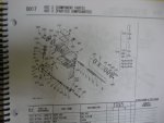
(My parts book 97898-41830 May 2007 pg D017 HST 2 Component Parts does not name all the parts, just called assemblies for groups of parts and is too small a pic to include.)
(I lied, took picture of page anyway.)
1 Red wire tie on HST rod for ease of adjusting and remembering where it was. I'm older, memory not good. Ha-Ha!
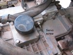
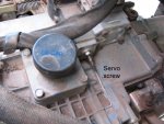
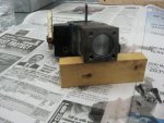
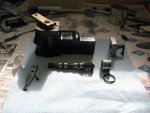
2 Servo screw.
3 Oil Cap / Servo screw
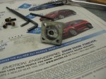
4 Servo assembly showing corrosion on lower side of piston with end cap removed. Assembly is laying on it's side so corrosion is in 3 o'clock position.
5 Closer view of corrosion, sorry little fuzzy.
6 End cap showing corrosion and position of adjuster up inside cap, just the way it was removed from RTV1100.
7 Piston is cleaned, somewhat, and reinstalled for testing. More cleaning before assembly.
8 Closer view of piston after some cleaning.
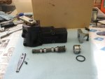
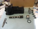
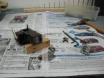
9 Exploded view after disassembly. Top (servo assembly and end cap with adjuster) Bottom (linking arm with pin and c-clip, servo rod and spring assembly, piston and seal)
10 Same as 9, box blocking sunlight, a little clearer.
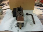
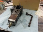
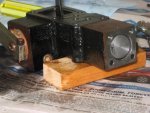
11 End view with plug removed for disassembley.
12 Another end view.
13 Parts book. (everyone has one, right)
14 The Future at speed. No, not mine.
What I did:
As you can see I removed the complete servo unit and took it apart, something I do best. Right away you notice the black on the end cap and on the end of piston. Also noticed adjusting screw was 1/4" up inside the adjuster, doing nothing. I had over adjusted. Nobody seem to know what was going on with this thing so I found out the hard way, take it apart. Actual took it apart for another reason, but not going there today. So then you see the complete picture of it all apart.
What I learned:
Asked a lot of questions on this unit and found out no one knows what I know now or would tell me. Perhaps a trade secret and the FBI will be at my door tomorrow. To bad, I live in Canada (oops, could be RCMP).Ha-Ha!
Where was I, oh yes, see that little black ring, that is called and o-ring. It is supposed to be black and round, which it is, but not a little hard (like 1/3 of it's life is gone) and a little disintegrated, although that is hard to tell in a picture. But I believe that is what was on the piston in the servo hole where the piston resides and on the end cap. Something ate up some of the o-ring and degraded it. Don't know, will probably never know, but do know it affected the alumininum end cap, the piston is etched as is the bore it sits in. Not much but some. And the piston was semi-stuck in the bore, in about 1.5mm. When I took the servo assembly off, and was playing with the lever you see in the exploded view, it kind of went pop and I felt it letting go. Only did it one time so I'm assuming the little piston was semi-frozen in one spot. When I was trying to adjust the screw it was not moving and because I thought it was at bottom, made adjustments outward, not realizing nothing was moving. But did realize all my adjusting had no effect or improvement in previous attempts.
Solution:
Replace o-ring and with fine sandpaper and light rubbing, polish up everything as nice as possible and clean it spotless. Looks much better. Sorry didn't take picture after cleaning, so can't prove my work, you will have to be dumb enough to trust me. Ha-Ha! LOL!
What I know:
Measured how far that little piston travels, 3.6-3.7mm from the top of bore to top of piston when inserted with rod assembly removed, so this is all the range of possible travel for this little piston. Americans hate MM, too bad, you do the math and convert. Then I set the adjusting screw flush with the bottom of the end cap, hand tightened the lock nut and measured the free length of bolt, which was 18.85mm. Then installed the end cap, tighten 4 end cap bolts and moved adjusting screw to max inward position and hand tightened lock nut and measured 14.8 mm of free bolt length. Did it this way so it is easiest to measure when on machine and lock nut is in place. Easiest way to get calliper measurement. Then I carefully counted the number of turns from dead bottom to all the way out (for the piston) and the screw moves 3 complete turns. Beautiful, placed a nail polish paint mark, no I don't wear nail polish, on the bolt when it was at dead bottom in and move it 3 turns out removed end cap and verified it was flush with end cap mating surface. Now I know at 14.8 to 16.1mm is 0-1 turns out, 16.1 to 17.4 is 1-2 turns out, and 17.4 to 18.8 is 2-3 turns out range. We ended up with 1.75 turns out as best results for our setup. I haven't re-tried this after all our testing yesterday, but initially when it was turned in, this is with everthing back together, you feel resistance then it bottoms, turning out after 1.5 to 2 turns it goes loose, in other words no push on the screw from the piston. Not sure why, don't care, just happy I know how it reacts and can live with this as I am no HST expert and don't know what is actually happening when in use. Perhaps hydraulic pressures move the piston out farther when running. Remember once set this piston probably never moves from that point on, until you find the need to readjust. And if you want to remove the end cap and check, it will not fly apart and it might be impossible to get the piston out with doing what i did as it is very tight. Don't ever put anything on this except UDT/SUDT as a lube because it is your HST and that's what should be there. It was dry from the o-ring out, but I put some in there at assemble time just because I like things oily!!! Ha-ha! And it may stop some corrosion.
Conclusion:
With my nail polish mark and measurement, I know exactly where mine is set, what the range is on the adjusting screw and can test in 1/16 of a turn increments to get the best performance from this machine. Once set it should never need adjusting for a long long time. Most are probably never touched after they leave the factory. Adjust the screw for best performance and then the HST rod for neutral. That's what we did.
What I don't know:
Between this and the HST netural rod, which should be done first and which last and why. Never heard a straight answer on that one, most technicians probably never even do what I just did so they don't know.
I think the RTV900 and RTV1100 have the identical setup for the servo adjustment. But for sure you can take measurements and check this out on the machine without doing what I just did, by adjusting bolt all the way in, remove end cap with bolt left where it was and measure, then back off bolt to flush position and measure, then you would know for sure.
After reading:
If you don't understand what I'm saying and what is happening here, you are probably not mechanically inclined enough to be fussing with this kind of stuff. DON'T BOTHER!
Pictures RTV1100 2009 60+ hours October 16 2010
I am not a Kubota mechanic or a HST expert, strictly a backyarder with tools. Often just smart enough to get myself in deep trouble!
(I don't take pictures for a living and don't write manuals for a living either so excuse the mistakes and fuzzy.)
(My parts book 97898-41830 May 2007 pg D017 HST 2 Component Parts does not name all the parts, just called assemblies for groups of parts and is too small a pic to include.)
(I lied, took picture of page anyway.)
1 Red wire tie on HST rod for ease of adjusting and remembering where it was. I'm older, memory not good. Ha-Ha!
2 Servo screw.
3 Oil Cap / Servo screw
4 Servo assembly showing corrosion on lower side of piston with end cap removed. Assembly is laying on it's side so corrosion is in 3 o'clock position.
5 Closer view of corrosion, sorry little fuzzy.
6 End cap showing corrosion and position of adjuster up inside cap, just the way it was removed from RTV1100.
7 Piston is cleaned, somewhat, and reinstalled for testing. More cleaning before assembly.
8 Closer view of piston after some cleaning.
9 Exploded view after disassembly. Top (servo assembly and end cap with adjuster) Bottom (linking arm with pin and c-clip, servo rod and spring assembly, piston and seal)
10 Same as 9, box blocking sunlight, a little clearer.
11 End view with plug removed for disassembley.
12 Another end view.
13 Parts book. (everyone has one, right)
14 The Future at speed. No, not mine.
What I did:
As you can see I removed the complete servo unit and took it apart, something I do best. Right away you notice the black on the end cap and on the end of piston. Also noticed adjusting screw was 1/4" up inside the adjuster, doing nothing. I had over adjusted. Nobody seem to know what was going on with this thing so I found out the hard way, take it apart. Actual took it apart for another reason, but not going there today. So then you see the complete picture of it all apart.
What I learned:
Asked a lot of questions on this unit and found out no one knows what I know now or would tell me. Perhaps a trade secret and the FBI will be at my door tomorrow. To bad, I live in Canada (oops, could be RCMP).Ha-Ha!
Where was I, oh yes, see that little black ring, that is called and o-ring. It is supposed to be black and round, which it is, but not a little hard (like 1/3 of it's life is gone) and a little disintegrated, although that is hard to tell in a picture. But I believe that is what was on the piston in the servo hole where the piston resides and on the end cap. Something ate up some of the o-ring and degraded it. Don't know, will probably never know, but do know it affected the alumininum end cap, the piston is etched as is the bore it sits in. Not much but some. And the piston was semi-stuck in the bore, in about 1.5mm. When I took the servo assembly off, and was playing with the lever you see in the exploded view, it kind of went pop and I felt it letting go. Only did it one time so I'm assuming the little piston was semi-frozen in one spot. When I was trying to adjust the screw it was not moving and because I thought it was at bottom, made adjustments outward, not realizing nothing was moving. But did realize all my adjusting had no effect or improvement in previous attempts.
Solution:
Replace o-ring and with fine sandpaper and light rubbing, polish up everything as nice as possible and clean it spotless. Looks much better. Sorry didn't take picture after cleaning, so can't prove my work, you will have to be dumb enough to trust me. Ha-Ha! LOL!
What I know:
Measured how far that little piston travels, 3.6-3.7mm from the top of bore to top of piston when inserted with rod assembly removed, so this is all the range of possible travel for this little piston. Americans hate MM, too bad, you do the math and convert. Then I set the adjusting screw flush with the bottom of the end cap, hand tightened the lock nut and measured the free length of bolt, which was 18.85mm. Then installed the end cap, tighten 4 end cap bolts and moved adjusting screw to max inward position and hand tightened lock nut and measured 14.8 mm of free bolt length. Did it this way so it is easiest to measure when on machine and lock nut is in place. Easiest way to get calliper measurement. Then I carefully counted the number of turns from dead bottom to all the way out (for the piston) and the screw moves 3 complete turns. Beautiful, placed a nail polish paint mark, no I don't wear nail polish, on the bolt when it was at dead bottom in and move it 3 turns out removed end cap and verified it was flush with end cap mating surface. Now I know at 14.8 to 16.1mm is 0-1 turns out, 16.1 to 17.4 is 1-2 turns out, and 17.4 to 18.8 is 2-3 turns out range. We ended up with 1.75 turns out as best results for our setup. I haven't re-tried this after all our testing yesterday, but initially when it was turned in, this is with everthing back together, you feel resistance then it bottoms, turning out after 1.5 to 2 turns it goes loose, in other words no push on the screw from the piston. Not sure why, don't care, just happy I know how it reacts and can live with this as I am no HST expert and don't know what is actually happening when in use. Perhaps hydraulic pressures move the piston out farther when running. Remember once set this piston probably never moves from that point on, until you find the need to readjust. And if you want to remove the end cap and check, it will not fly apart and it might be impossible to get the piston out with doing what i did as it is very tight. Don't ever put anything on this except UDT/SUDT as a lube because it is your HST and that's what should be there. It was dry from the o-ring out, but I put some in there at assemble time just because I like things oily!!! Ha-ha! And it may stop some corrosion.
Conclusion:
With my nail polish mark and measurement, I know exactly where mine is set, what the range is on the adjusting screw and can test in 1/16 of a turn increments to get the best performance from this machine. Once set it should never need adjusting for a long long time. Most are probably never touched after they leave the factory. Adjust the screw for best performance and then the HST rod for neutral. That's what we did.
What I don't know:
Between this and the HST netural rod, which should be done first and which last and why. Never heard a straight answer on that one, most technicians probably never even do what I just did so they don't know.
I think the RTV900 and RTV1100 have the identical setup for the servo adjustment. But for sure you can take measurements and check this out on the machine without doing what I just did, by adjusting bolt all the way in, remove end cap with bolt left where it was and measure, then back off bolt to flush position and measure, then you would know for sure.
After reading:
If you don't understand what I'm saying and what is happening here, you are probably not mechanically inclined enough to be fussing with this kind of stuff. DON'T BOTHER!
Attachments
-
 IMG_1108_servo_screw.jpg82.6 KB · Views: 297
 -
 IMG_1108_servo_screw_oil_cap.jpg96.4 KB · Views: 288
 -
 IMG_1109.jpg94.9 KB · Views: 286
 -
 IMG_1110.jpg95.2 KB · Views: 278
 -
 IMG_1111.jpg96.1 KB · Views: 282
 -
 IMG_1112.jpg94.2 KB · Views: 279
 -
 IMG_1113.jpg94.2 KB · Views: 275
 -
 IMG_1114.jpg96.9 KB · Views: 276