SpudHauler,
I'm not sure where I picked up those other pressures I posted earlier.
Just found the relief pressure spec description in my downloaded RTV 900 Service Manual that I paid $10 for on site
http://kubota.servicemanualvault.com/
"The relief pressure is set in between 25.5 to 26.5 MPa (260 to 270 kgf/cm2, 3698 to 3840 psi) when shipped from the factory. But, for the purpose of after-sales services, as it is impossible to reset the pressure precisely as set in the factory, its setting range is defined as a slightly wider range between 22.6 to 26.5 MPa (230 to 270 kgf/cm2, 3271 to 3840 psi)."
So based on this, it looks like the factory is setting that relief pressure between 3698 and 3840 psi.
I didn't want to have to take my unit to the dealer to have my pressures checked because of the hassle. I've never had shifting problems, once in a while I'll have to press on the brake. So, based on that, and since I only have 65 hours on my 2010 RTV 900, I was assuming my neutral adjustment on the servo was OK. I have no way of knowing what my relief pressure is set at. I'd like to think if I had the right gauges, fitting and tools I could do check it myself, but the procedure sounds involved on the relief pressure adjustment. My experience with any kind of dealer service shops has not been satisfactory. I may just drop by my local Kubota dealer and chat with the service technician to get a feel for their experience.
Jumping back a few posts, I thought I'd share my lessons learned from DIY relieve pressure checking. If you are not comfortable with high pressure hydraulics, do not attempt this. Every component in the test line must be rated above the expected pressure. A hydraulic pinhole leak is not something to mess around with. It will mess you up. I will not describe every detail, because I assume you will be doing this with a WSM nearby.
First you need some calibrated, high resolution pressure gages. El cheapos from tractor store will not suffice. You are checking for target values, so the gages need to be calibrated, and they need to have adequate resolution so you're not guessing halfway between two marks. A digital gage would be better because you don't have to plumb a hydraulic hose into the system, and they usually include a filter to dampen minor pressure fluctuations.
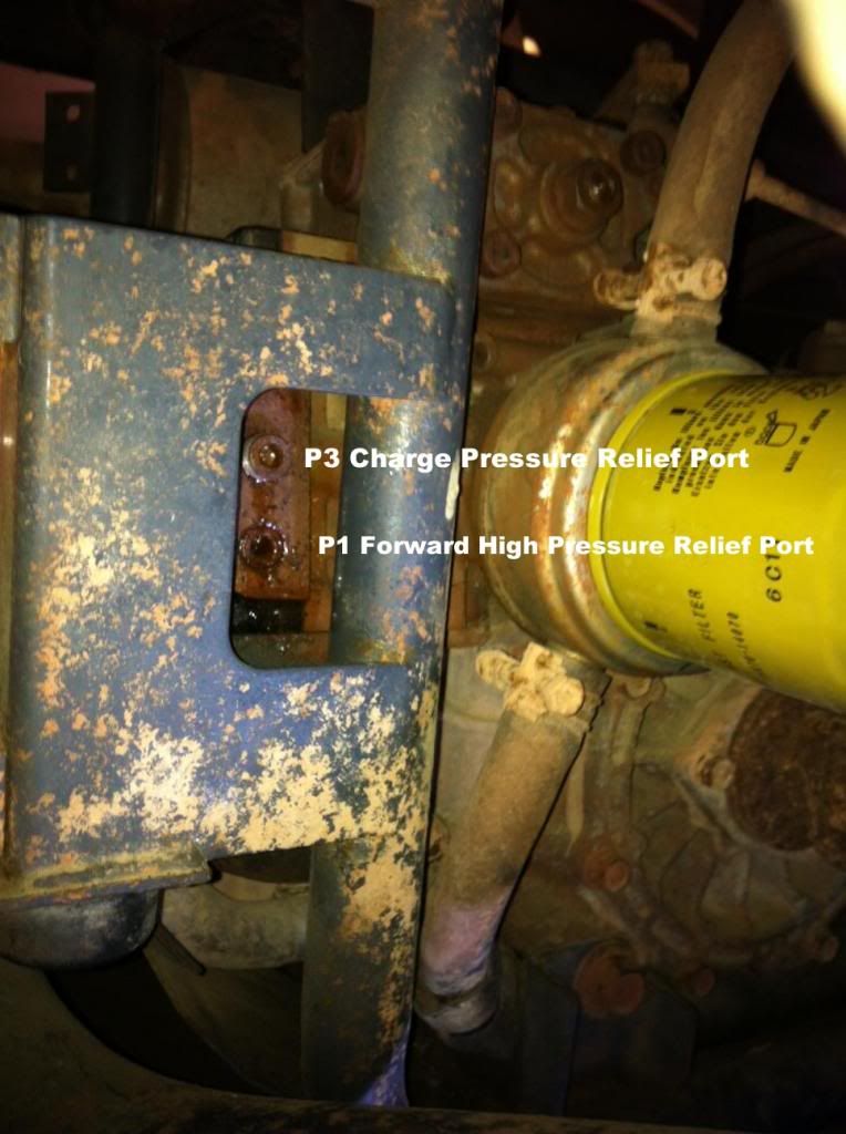
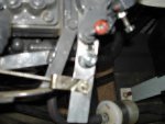
The first challenge is removing the allen head port plugs. They are sealed with a thread sealant similar to lock-tite, so they usually feel like they are stuck. Be very careful, or you'll round out the recessed allen hex. I usually scrape around the edges with a dental pic to break away any corrosion between the male and female threads, and then soak with penetrating fluid and cross your fingers.
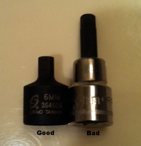
The allen hex is 6mm. I recommend a stubby impact version because they are less likely to twist off. I found a good set with SAE and metric sizes in 3/8" drive.
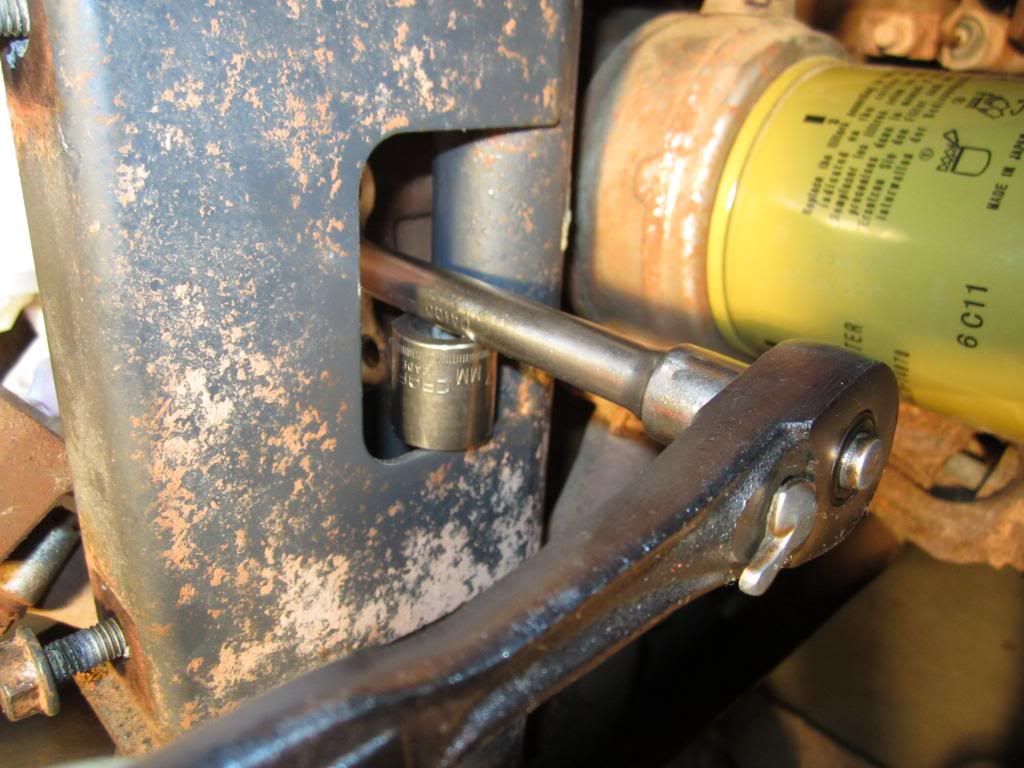
I also recommend blocking the extension with another socket. This provides pure torsion to the plug and further eliminates the chance of rounding the recessed allen hex or twisting off the allen bit. You will have to play around to find the proper gadgets to block with. A socket seemed to work for the forward high pressure port plug.
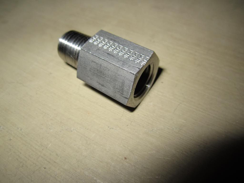
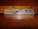
If you are lucky enough to get the plug out without tearing everything up, then you will likely need an adapter for the next step. The plug is not a standard National Pipe Taper (NPT) plug. I believe it is British Standard Pipe Taper (BSPT). They are nearly identical, but differ by one thread per inch and the thread angle. I ordered a 1/4" BSPT to 1/4" NPT adapter, so I can install my hydraulic hose and pressure gage. Keep in mind, the adapter fittings must be rated for the expected pressure too.
If you get this far, you are home free. Follow the remaining procedure in the manual and test your relief pressure.
Adjusting the relief pressure is not too bad, but be VERY careful. Minor adjustments could result in dramatic pressure increases which would not be good. Following the procedure in the WSM, remove the 10mm hex plug for the forward or reverse relief. Fish the check spring and relief valve out of the hole with a CLEAN magnet or needle nose pliers. Do not scar anything.
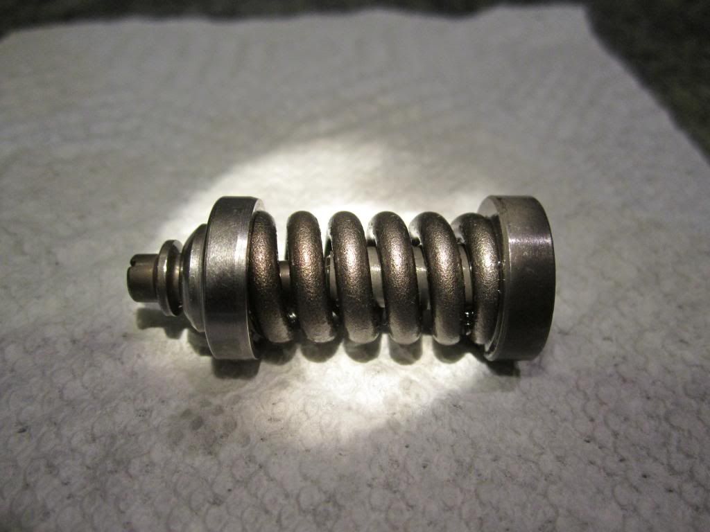
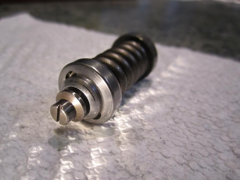
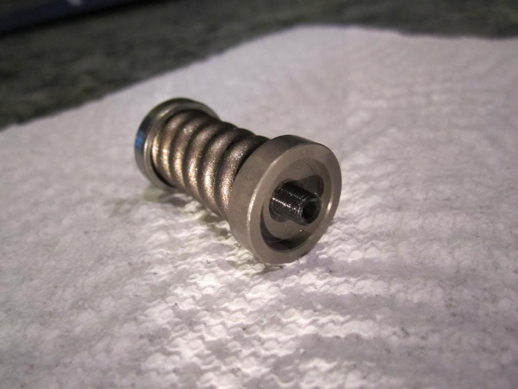
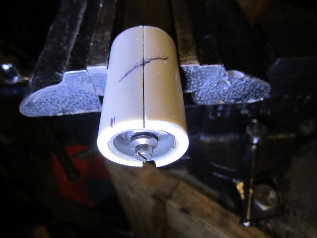
The valve is basically a preloaded spring trapped between two precision diameter seals. The preload force in the spring must be overwhelmed by the hydraulic pressure in order to unseat the seal. The trapping mechanism is a fine threaded fastener. One end of the fastener is a flathead screw forming the male threaded portion. The first seal freewheels/spins on this male threaded portion. The other end of the fastener is a female threaded collar, integral with the other seal. A 2.5mm allen hex acts like a lock nut.
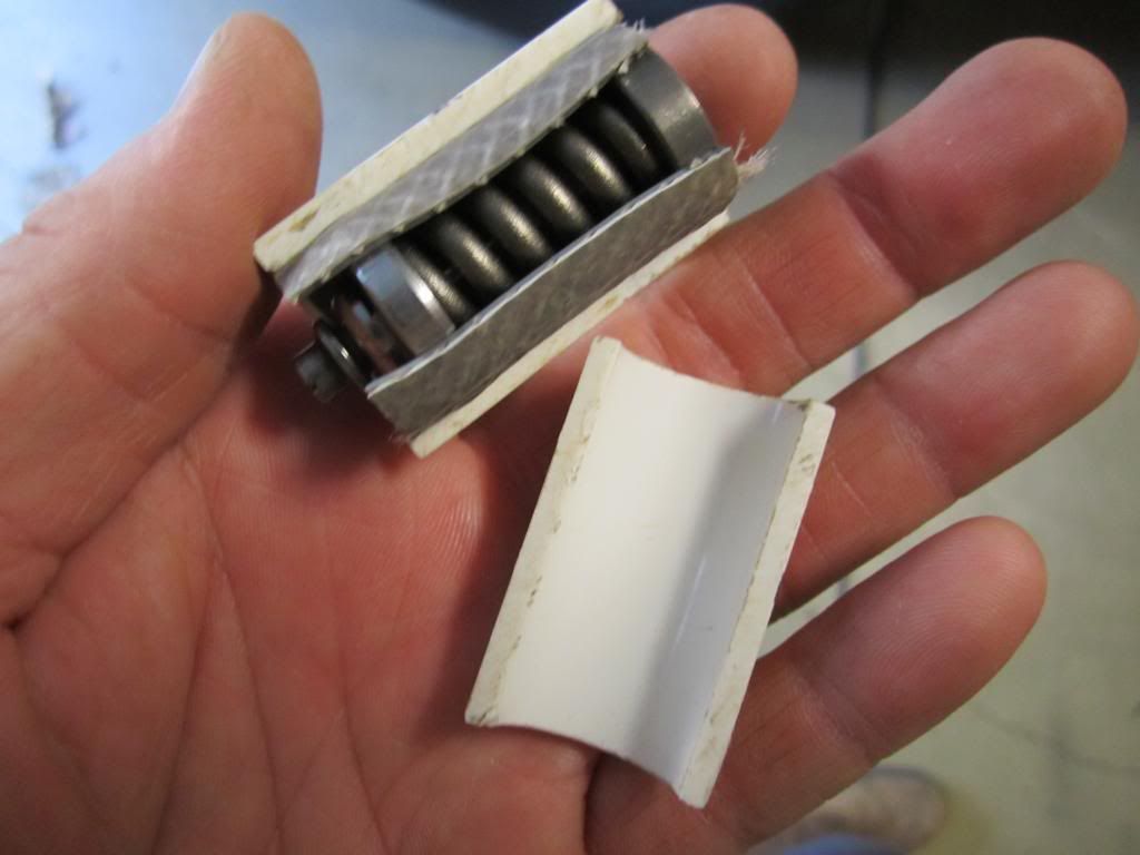
I only adjusted my reverse relief pressure. To protect the sealing surfaces, I cradled the valve inside a piece of garden hose sheathed with PVC. Clamp the seal most near the allen lock nut in the vice. Loosen the lock nut, turn the flathead screw, retighten the lock nut. It's that simple. I would recommend adjusting 1/16 of a turn, reinstall and test relief pressure. It's better to creep up on your desired setting than to overshoot.