Radiator Fan

fuzzie

New member
It;s about to go into the pond! 2014 RTV 1100, radiator fan won't come on. I've checked the fuse (actually checked all of them, because I found it hard to believe the radiator fan was a 30 amp fuse). I checked the relay (again, I checked them all because I couldn't confirm which relay it was). They're all good. I replaced the temperature sending unit. When I connect the fan direct to 12 volts, it works.
Any other suggestions, other than the pond?
Thanks!
 
Take out relay and jump 12 volt from the relay plug to the wire leading to fan motor... if fan runs then check the 12 volt supply to the relay plug? If that passes swap relay with another and test again. If that fails you have a bad ground or the wire from sender to relay plug is bad
..
 
Thanks! I can't even figure out which relay it is to test it.
So, if I disconnect the temp sensor, and connect my multimeter to that wire (white), I get continuity to the chassis, and to the black wire going to the fan. But, get this, if the fan is connected, I also get continuity to the white wire, which should happen.
 
 
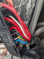
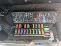
I have a box of 6 relays with one empty above the fuse box. No lid, no labels. I have a box of 6 relays with one empty below the fuse box, again no lid or labels. I removed all 10 relays, tested them and put them back. No chance they were put in the same location. The 30 amp fuse is good. Well, all the fuses are good. It's killing me! I can't find a diagram of the 2 relay boxes anywhere.
 
1000003076.jpg
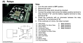
I still can't identify which relay it is. None match the colors in the diagram.
 

Attachments

  • PXL_20250819_193704244.jpg
    PXL_20250819_193704244.jpg
    1.3 MB · Views: 3
  • PXL_20250819_193708677.jpg
    PXL_20250819_193708677.jpg
    1.5 MB · Views: 3
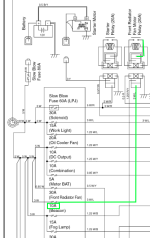
Ok, it appears you are chasing the incorrect fuse. The fuse for the front radiator fan is a 10 amp, not a 30 amp. I have included a high lighted schematic clip that shows the fan receives it's 12 vdc from a 10 amp fuse. The fuse rating for the circuit is shown under the fuse. The descriptor is shown on top of the fuse. The relay coil gets it's signal power from a radiator fan motor switch, which I am assuming that is a thermistor of some sort that goes into a sensor well in the radiator. The temp sensor switch is supplied by a 5 amp fuse. Hope that helps a bit.

Screenshot 2025-08-21 at 10.44.21 PM.png
 
Ok, it appears you are chasing the incorrect fuse. The fuse for the front radiator fan is a 10 amp, not a 30 amp. I have included a high lighted schematic clip that shows the fan receives it's 12 vdc from a 10 amp fuse. The fuse rating for the circuit is shown under the fuse. The descriptor is shown on top of the fuse. The relay coil gets it's signal power from a radiator fan motor switch, which I am assuming that is a thermistor of some sort that goes into a sensor well in the radiator. The temp sensor switch is supplied by a 5 amp fuse. Hope that helps a bit.

View attachment 16059
Either the schematic is incorrect or I am. I took another look and it shows it connected to a 30 amp. Damn designers have zero drawing standards......

Quick Question: Is the relay coil being energized for the front fan? Is the rear radiator fan running? Both fan relays are fed a single signal to their coils from the temp switch, being fed by the 5 amp acc fuse. The signal to the rear fan is running through a diode before it goes to it's relay coil. The front fan does not have a diode. The 5 amp fuse gets it's power when the key switch is turned to the "on" position. Both fans can also be turned on by the AC compressor, via a circuit diode.


1755839836048.png
 
Last edited:
I was excited about it just being a fuse. So I pulled them all and tested all of them. Damn, they're all good.
Front fan works fine. I might drive it into the pond today!The bass need some good cover.
 

Attachments

  • PXL_20250822_201831665.jpg
    PXL_20250822_201831665.jpg
    1.7 MB · Views: 2
So, in your original post, you just stated it was a radiator fan. You never said which one it was. If it is the rear fan that won't run, you have a diode in the circuit for the rear fan. If the diode is burned out, the front fan will still run, but the rear fan won't.
 
I don't, but if I had to guess, it would be in the same compartment or general vicinity with all of the relays. The schematic calls it "radiator fan diode 2"

I did find a relay layout located under the "passenger?" seat.Screenshot 2025-08-23 at 6.58.12 PM.png
 
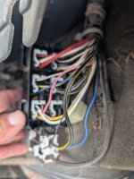
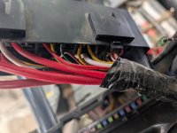
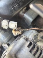
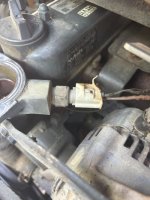
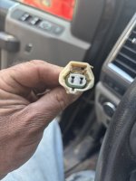
Thanks for all the help...turns out I was testing the wrong temp sending unit. See the photos attached that show the one I should have been tested, that is toast! I cut the bad wires, connected them together, and fan comes on. Now I need to find a new plug. Kubota tells me it has been discontinued.
 

Attachments

  • IMG_4851.jpg
    IMG_4851.jpg
    48.9 KB · Views: 7
  • IMG_4850.jpg
    IMG_4850.jpg
    37.2 KB · Views: 7
Your Google skills much be far better than mine! I've even gone down the AI rabbit hole and I can't find this connector anywhere. A lot are close, but none with that weird tab on the bottom.
 

Attachments

  • plug.jpeg
    plug.jpeg
    2.6 MB · Views: 2
Your Google skills much be far better than mine! I've even gone down the AI rabbit hole and I can't find this connector anywhere. A lot are close, but none with that weird tab on the bottom.
I cross reference plugs and receptacles all the time at work. Many different connector receptacles are made by just a hand full of manufacturers. If you can cross reference the temp sending unit and find out who actually manufactures it, cross referencing the receptacle is fairly easy. Start with the Kubota part number for the temp sensor. Cross reference it to see who else manufactures that sensor. Chances are Kubota doesn't make their own sensors. They design it with a common on the shelf catalog sensor that meets their temp, thread size, etc specifications made by a large sensor global manufacturing company. With a part cut-sheet, it should tell you what type of connector it uses.

Or.........just cut the wires off of the bad receptacle, strip them back, solder and heat shrink the wires directly onto the sensor. Problem solved and down the trails you go with both fans running. If the sensor ever goes bad again in 15 years, do the same thing again. Sometimes, manufacturers try to convince us we need to live in a plug-and-play world, that any part can go obsolete at any time. In the manufacturing world, that is called "Planned obsolescence" A majority of consumers are duped into thinking that they need to replace the whole vehicle, just because they can't get one part anymore from the dealer.


There is always a technical work around. You just need to think: What would Derek on Vice Grip Garage do?
 
Last edited:
Top